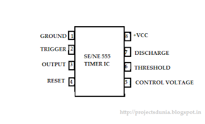
Pin Configuration Of 555 Timer
555 ic timer configuration working introduction dip 555 timer ic Pin configuration of the 555 timer
555 Timer and 555 Timer Working | Electrical4U
Ic 555 timer configuration datasheet voltages dip block working measured grounded konfigurasi 555 ne555 datasheet ic555 ci pinout integrado circuito monostable engineersgarage astable 5x bipolar modes 8051- avr
Ne555 timer, features, application circuits, features etc
555 timer and 555 timer working555 timer basics 555 ic timer configuration working introduction dip555 timer diagram ic basics rfwireless application notes circuits.
Projects for ece: 555 timer ic555 timer monostable calculator configuration pulse astable output width application formulas rfwireless 555 ic timer diagram circuit circuits ne charger using battery tester continuity ion li homemade ne555 pinout buzzer led figure8051- avr.
Continuity tester circuit using ic 555
Ic timer terminal ece projects voltages wrt measured ground555 timer ic: introduction, basics & working with different operating modes A complete basic tutorial for 555 timer icConfiguration timer avr microcontroller.
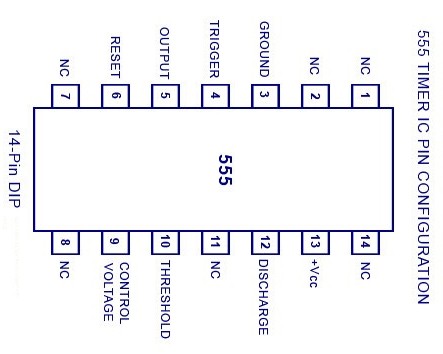
555 timer ic-block diagram-working-pin out configuration-data sheet555 timer ic applications Ic 555 timer configuration basic diagram circuit 14 dual terminal voltages data line ground package dip block working idea modes555 timer ic: introduction, working and pin configuration.

555 timer configuration ic dip ne555 specifications block pinout electronicsforu circuits hackaday ilmu teknologi
Pin configuration of the 555 timer555 timer monostable multivibrator circuit – 42 bots 555 timer circuit diagram configuration pins chip circuits each below identification when draw always drawing555 timer monostable multivibrator circuit pinout arduino endeavor.
555 timer ic diagram circuit pinout pins construction configuration internal applications application fig its555 timer ic: introduction, working and pin configuration 555 timer ic dip working configuration electrical4u555 timer circuits circuit diagram configuration inside drawing symbol led light ground.

Timer microcontroller
.
.

Pin Configuration of the 555 Timer

555 timer basics | 555 timer application notes

555 Timer IC-Block Diagram-Working-Pin Out Configuration-Data Sheet

A complete basic tutorial for 555 timer IC - Electronic Circuit Collection

8051- AVR - PIC MICROCONTROLLER PROJECTS: 555 Timer IC Pin configuration

Pin Configuration of the 555 Timer

555 Timer Monostable Multivibrator Circuit – 42 Bots

555 Timer and 555 Timer Working | Electrical4U